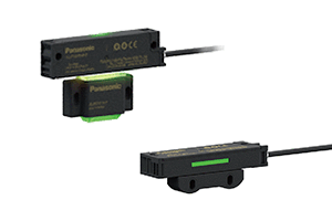
Door Switch SG-P
Liên hệ: 0243 8 771 700
![]()
UL , CE , CSA , TUV Approved
UL, CSA : Certified by TÜV SÜD America Inc. (NRTL)

- Miễn phí vận chuyển
- Hỗ trợ kỹ thuật 24/7
- Bảo hành 1 năm, chăm sóc trọn đời
Large and Bright Indicators Show the Open / Close Conditions of All Equipment Doors.
When one of the safety switches connected in series enters a non-detection state, the indicators of all other safety switches flash in green to notify the operator.
|
|
Two Types to Choose from
|
|
Flashing Function Notifies Unsafe Condition
When a door is intentionally kept open, the indicator of the safety switch on that door changes to red and the indicators of the safety switches on all other doors flash in green.
The operator can recognize immediately the equipment status and which door is open.
|
|
|
|
Actuator with Industry’s First*
“Indicator Light Pass-through System”
|
The visible type actuator allows the light from the switch body to pass through so that the indicator light is visible from the actuator side. |
 |
Master-Slave (Standard / Sub) System for Reduced Wiring
Serial Connection of Up to 30 Units without Dedicated Controller
The SG-P series standard units, which are used as master units, can output safety signals all at once (OSSD1 / OSSD2).
The sub units used as slave units minimize the wiring for a cascade connection.
There is no need to purchase a dedicated controller. The presently used safety controller / circuit can be connected directly. Up to 30 units can be connected, thus contributing to wire-saving.
|
No Cumbersome Manual Pairing Necessary before Installation
* High-code models (SG-P20□-M-□, SG-P20□-S) only
During the initial setting, bring the switch body close to the actuator and turn on the power to let the safety switch detect the actuator for 3 seconds. This simple procedure completes the pairing. In a cascade connection, pairing can be achieved all at once by simply turning on the power. This reduces the man-hours required for starting up the equipment.
* Low-code models (SG-P10□-M-□, SG-P10□-S) do not require pairing.
|
Helps Prevent Intentional Deactivation of Safety Function
The ISO 14119:2013* international standard stipulates a design requirement that deactivations of safety functions shall be minimized.
Export of equipment sometimes requires to meet this standard. The SG-P series products are available with two different coding levels: High-code models and Low-code models. The High-code models are compatible with ISO 14119* coding level (high level coded actuators) and prevent intentional deactivation of their safety function.
* ISO 14119: Safety of machinery – Interlocking devices associated with guards – Principles for design and selection
|
 Maintenance Actuators SG-PK-M Series (Sold separately)
Simple and Easy Maintenance!
 |
Renewal of maintenance procedures by eliminating the use of potentially dangerous deactivation tool (dummy or spare key)Desired maintenance mode can be easy constructed by mounting the coded actuator to the switch body.
|
One-touch Installation and Easy Construction of Maintenance Mode
Mounting the maintenance actuator to the SG-P unit enables the control output function for the maintenance mode.
The following two types of maintenance actuators are available:
Overall maintenance type (SG-PK-M1)
Individual maintenance type (SG-PK-M2)
■ One-touch installation
 * Individual maintenance type actuator (SG-PK-M2) is mounted on a compact type unit in the above example. |
Indicating the name of the department that owns the maintenance actuator and the name of person in charge on a commercially available key tag and attaching it to each unit makes it easy to manage the users. |
|
| * | Be sure to evaluate the control output correctly. |
|---|---|
| * | Can be used only with the standard switch body. |
| * | All switch bodies in series connection change to the maintenance mode. |
| * | The indicators on the switch bodies in series connection change in color. |
| * | All doors with the switch bodies in series connection can be opened and closed. Take care not to allow unauthorized persons to open or close the doors. |
|
| * | Be sure to evaluate the control output correctly. |
|---|---|
| * | Can be used with the standard or sub switch body. |
| * | Can be installed to multiple switch bodies for simultaneous use. |
| * | Only the switch bodies installed with this product type can be individually changed to the maintenance mode. |
| * | The indicators on the switch bodies in series connection change in color. |
Large and Bright Indicator for the Notification of Maintenance Mode Status to Workers
When the SG-P unit is mounted with the maintenance actuator, the large indicator lights in “yellow”.
The workers can readily recognize that the equipment is in maintenance.
|
Hãy chọn KSMC:
- Bảo hành sản phẩm 1 năm, chăm sóc khách hàng trọn đời
- Sản phẩm giá cạnh tranh, rẻ nhất tới tay khách hàng
- Sản phẩm chất lượng chính hãng.
- Đội ngũ nhân viên chuyên nghiệp,tận tâm
- Tiến độ chính xác, cam kết hàng cấp ra chính hãng


 Maintenance Actuators SG-PK-M Series (Sold separately)


Đánh giá
Chưa có đánh giá nào.